AUTHOR: AMIT JHA
The concept of electric vehicle first emerged in mid-19th century. However, with the development of internal combustion engine (ICE) technology, and lower price of oil, the fuel based vehicle became the more economical choice for consumer than the electric vehicle. In the last few decades due to the large environmental impact and the unstable prices of the petroleum the focus has turned back on electric vehicles. Many automobile companies like BMW, Tesla, and Renault etc. have introduced electric vehicle (EV) or hybrid electric vehicles (HEV) in the market and are putting in lots of research to develop these cars. The demand for electric vehicles in the last years has grown at a 60 % rate and is predicted to sustain that in the coming years, but to keep this rate is difficult [1]. With the rapid development of technology, if we succeed in lowering the price of motor drives and battery packs, the growth rate can be maintained.
Other than the source/type of power supply the performance/cost of the electric vehicle largely depends on the performance of the drive unit. The drive unit comprises the inverter, motor, and gearbox. The design of the inverter and motor are very much inter-dependent. For example, size of inverter and its control depend on the type of motor and its parameters, or vice versa. Also, the design of gearbox influences the design of motor and vice versa. Therefore, for optimum performance of the EVs the selection of motor type is very important.
Figure 1 shows the basic block diagram of the drive unit in any traction application. The arrangement of different components and their interface can vary from vehicle-to-vehicle but the basic working principle is the same. The power supply can be an ultra-capacitor, a battery, or direct overhead lines (like in trains). In hybrid vehicles it can be from gasoline or from fuel cells. The role of the inverter is to regulate the supply power, as per the load requirements, of the motor. The motor will then transform electrical power to mechanical power. The gearbox scales the mechanical power from high speed low torque from motor to high torque low speed at the wheel. The higher the gear ratio, the smaller the size of motor. Well some drive system can be without gearboxes called “Direct Drive” but it is not common in electric vehicles yet. To have better control some sensors like thermocouple, speed sensor, position sensors etc. (for PM motors) are placed on motor and gearbox which give feedback to the control unit. Based on these sensors’ the input, the inverter supplies the power to motor accordingly.
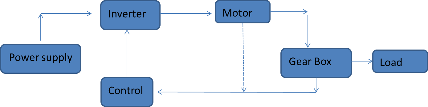
Figure 1: Basic Block diagram of a Drive unit
Figure 2 shows a typical load profile that is expected for a traction motor to fulfill. It is important to note that the motor very rarely follows the torque speed curve during operation. These curves can be looked as enveloping all load points. The complete load cycle can be divided into three sections depending on the speed.
- Constant Torque: The motor is required to provide constant torque up to a certain speed called “Base speed”. There are different names for this speed used by different organizations. Generally, this is the speed where inverter output voltage reaches its limit. So its obvious we want higher torque at low speed because the higher the constant torque, the higher then the acceleration of the vehicle.
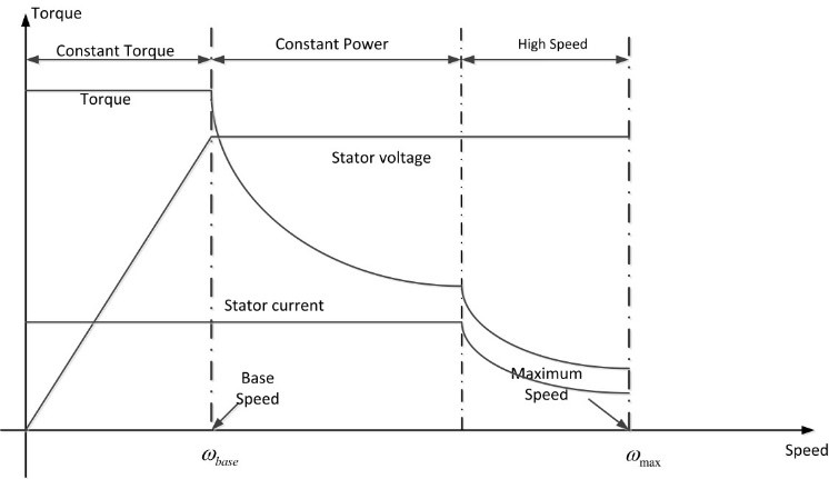
Figure 2: Typical Torque speed curve of a Traction Motor [http://www.intechopen.com/]
- Constant Power: This is the speed range where the motor is expected to deliver constant power. When the motor speed reaches base speed the inverter also reaches it maximum voltage and the current is also at maximum. Therefore, the inverter cannot supply any further power to the motor and hence it is called ‘constant power region.’ This is also referred as “Flux weakening zone”. The reason is that if we want to increase the speed of the vehicle above base speed, then the output torque of the motor has to be decreased. Hence the flux is weakened to achieve reduction in the torque.
- High speed region: This is the region where speed of the vehicle is increased very high but as can be seen from the Figure 2 the power cannot be kept constant in this region and hence the inverter reduces the current to the motor.
The electric motors in traction application are required to operate in different ways in different speed range. In ideal world we want a motor, which can generate very high starting torque, has very large constant power range and can also achieve high speed range. However, in reality it is hard to achieve all three mentioned properties in the same motor. For example, the surface mounted PM motor offers very good high starting torque but the constant power range is not so good.
The different types of the motor used for traction are Induction motor (IM), permanent magnet synchronous motor (PMSM), Switched reluctance motor, etc. Each motor has its pros and cons depending on the operating conditions and the requirements.
Now we have understood that motor is an integral part of the drive system. To make the situation even more confusing, there are many different types of motors available for the traction applications. Furthermore, each motor design can perform in certain speed range better than the other speed range. The design or selection process of motor is very complex, time consuming and largely inter-dependent on the other components of the drive unit.
In the next blog I will present and discuss some of the motors used in traction application. I will also compare them. So stay tuned….
Bibliography
| [1] | Tom Randall. (2016, Feb) Bloomberg. [Online]. http://www.bloomberg.com/features/2016-ev-oil-crisis/ |
| [2] | Narayan C.Kar Gaurav Nanda, “A survery and comparison of characteristics of motor drive used in Electric Vehicles,” IEEE. |
| [3] | L. Chang, “Comparison of AC drives for Electric Vehicles-A report on Expert’s opinion Survey,” IEEE, 1994. |
| [4] | R.J.Hill, “DC and AC Traction Motors,”. |